|
|
|
cylinder through a wall at an angle
Thursday, October 29 2009
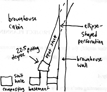
Among other things, today I was faced with the problem of routing the vent stack from the composting basement of the brownhouse up high above the roof. I had decided to use four inch PVC and HDPE sewer pipe for this stack, and to keep it as vertical as possible while avoiding any holes in the roof. This meant angling it slightly from vertical outward and past the east gutter. I'd cut a hole in the shitting bench for the stack to rise from, but not far above this there would have to be a fitting to send the stack off at a minimal angle. With four inch sewer pipe, the smallest angle of fitting you can buy is 22.5 degrees (which is smaller than I've seen for more conventional sizes of PVC). So I planned to use a 22.5 degree fitting to send the pipe out through the wall. But at that point I faced a problem: what shape hole does a cylindrical pipe make when it goes through a vertical wall at an angle of 22.5 degrees? I figured it would be something of an ellipse, but in the context of carpentry, an ellipse is a very imprecise thing. There are no tools to predict the shape of ellipses, let alone cut them.
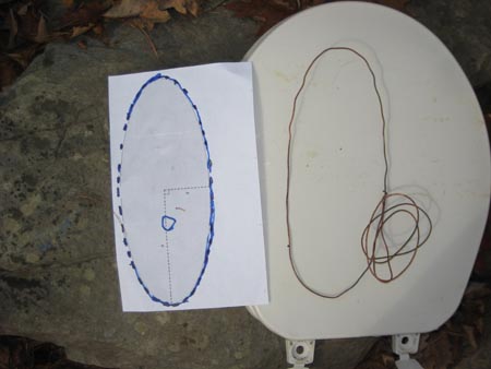
As a first stab at a solution, I laid out the pipes flat in the driveway to produce a simulation of how they would first bend at the fitting and then encounter the wall (for which I used a long straight board as a standin). Then, for a rough approximation of the hole I'd need to make, I wrapped a piece of copper wire around the pipe at precisely the place where it encountered the board standing in for the wall. The crude ellipse that resulted could be used as a model for the shape of the hole I'd need to cut if all else failed. But I wanted to do better.
So I turned to the web, looking to find a convenient ellipse calculator (if such a thing existed). Ideally, the tool would take the diameter of the cylinder and the angle with which it was encountering a plane as parameters and then produce a plot of the resulting ellipse that I could cut out and use as a template. It turns out, however, that there are no such tools online (though I wasn't the only one looking; evidently such a tool would also be useful for the makers of custom bicycles).
In cases like this, it's not long before I find myself turning to Wolfram Alpha, a website from the authors of Mathematica which claims to be something of a web-based math tool and all-around data miner. It's not as good as it would like you to believe, though it does have its random talents. For example, it makes for a tidier and more graphically-helpful display of weather information for a zipcode than Weather.com. I tried typing various strings into the Wolfram "search engine," hoping it would attack the underlying math of my problem. Ultimately, the seach that got me closest to a solution for my problem was "ellipse eccentricity." At that point, I was presented with a handy tool where I could type in the semimajor and semiminor axes and it would plot me an ellipse. All I had to know was what the values for these were. I soon realized that I knew the value for the semiminor axis: 4.3 inches, (the outside diameter of the sewer pipe), since the width of the cylinder's hole remains the same no matter the angle at which it intercepts a plane. It's the semimajor axis that is tricky, since it smudges out wider and wider as the angle of incidence decreases. But then it occurred to me that I could calculate this from simple trigonometry. The semimajor axis (a) can be derived from the semiminor axis (b) and the angle of incidence (θ) with this equation:
a= b/tan θ
This gave me a semimajor axis of 10.3811 inches, which I could then feed to Wolfram Alpha for a plot. The resulting graphic is crude, but you can then download a version of the results for Mathematica itself (a process reached through the "Live Mathematica" link), and this gives you a document with an ellipse you can interactively resize. Maximized as large as I could make it, I then took the ellipse into Photoshop, made it precisely the size I needed it to be, and then printed it out as a template for use in the brownhouse. As a check for my work, this template closely matched the crude loop of copper wire I'd prepared experimentally, without the assistance of mathematics.

Today's napkin diagram.
 The copper wire ellipsis and the one generated by Mathematica. The copper one is somewhat larger because it was impossible to force it tightly against the four inch vent stack. The toilet seat provides scale and a helpfully light-colored background.
For linking purposes this article's URL is:
http://asecular.com/blog.php?091029 feedback
previous | next |

 The copper wire ellipsis and the one generated by Mathematica. The copper one is somewhat larger because it was impossible to force it tightly against the four inch vent stack. The toilet seat provides scale and a helpfully light-colored background.